Opens a window that lets you add a rectangular or radial grid of construction lines in the model.
General Information
Step-By-Step
Tips and Tricks
Related Tools
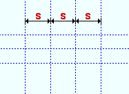
X spacings: When the " Rotation " is ' 0 ', this is the positive or negative (-) horizontal distance between vertical construction lines. Positive spacing is measured from left to right beginning at the point located in step 2 . Negative spacing is measured from right to left.
" X spacing " = ' x '. Vertical construction lines in the grid are spaced the distance that is the " X spacing ."
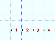
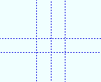
Number of lines: The quantity ( 1 or 2 or etc.) of vertical construction lines in the grid when " Mirror X " is not checked.
" Number of lines " = ' 4 '. If this number had been ' 2 ', only the construction lines marked 1 and 2 would have been generated.
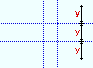
Y spacings: When the " Rotation " is ' 0 ', this is the positive or negative (-) vertical distance between horizontal construction lines. Positive spacing is measured from down to up beginning at the point located in step 2 . Negative spacing is measured from up to down beginning from that same point.
" Y spacing " = ' y '. Horizontal construction lines in the grid are spaced the distance that is the " Y spacing ."
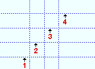
Number of lines: The quantity ( 1 or 2 or etc.) of horizontal construction lines in the grid when " Mirror Y " is not checked.
" Number of lines " = ' 4 '. If this number had been ' 2 ', only the construction lines marked 1 and 2 would have been generated.
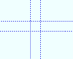
Rotation: 0 or a positive or negative (-) number of degrees. Rotation is around the reference point located in step 2 . ' 0 ' designates no rotation and results in a grid of perfectly horizontal and vertical construction lines. A positive number of degrees is measured counterclockwise from horizontal. A positive number of degrees is measured clockwise from horizontal.
Rotation = 0
Rotation = 45
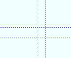
Mirror X: or . If this box is checked ( ), duplicates of the vertical construction lines are mirrored with respect to the reference point placed in step 2 . In the example below, the middle construction line is not mirrored because it runs through the reference point. If the box is not checked ( ), the number of vertical construction lines is the " Number of lines " entered for the X direction.
Mirror X
Mirror X
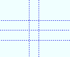
Mirror Y: or . If this box is checked ( ), duplicates of the horizontal construction lines are mirrored with respect to the reference point placed in step 2 . In the example below, the middle construction line is not mirrored because it runs through the reference point. If the box is not checked ( ), the number of horizontal construction lines is the " Number of lines " entered for the Y direction.
Mirror Y
Mirror Y
Circle radius spacing: A distance or comma-separated distances . Comma-separated entries disable (gray out) the " Number of circles " field.
The distance (in the setup " Units " or other units ) that defines the radius of the inner construction circle from the point located in step 2 . The second-to-the-most-inner construction circle will have a radius of twice this distance, the third three times this distance, and so on. Comma-separated distances may be entered to specify multiple radii measured from that same point. For example, an entry of 12, 36, 84 creates three construction circles with the given radii.
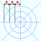
" Circle radius spacing " = ' s '. Adjacent construction circles are this distance apart from one another if measurement is taken along any line through the center of the circles.
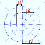
" Circle radii " = ' r1 ', ' r2 ', ' r3 '. The radii of the three construction circles are as specified.
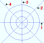
Number of circles: 0 or 1 or 2 or 3 or etc. This field sets the total number of construction circles that will be generated.
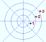
" Number of circles " = ' 3 '. If this number had been ' 2 ', only the construction circles marked 1 and 2 would have been generated.
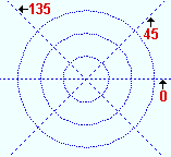
Radial line starting angles (degrees): A number of degrees or a series of comma-separated numbers . Comma-separated entries disable (gray out) the " Increments of " and " Number of radial lines " fields.
' 0 ' sets the starting construction line to be perfectly horizontal. A positive number of degrees is measured counterclockwise from horizontal. A negative number of degrees is measured clockwise from horizontal. Comma-separated numbers place radial lines that are rotated the specified numbers of degrees.
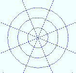
Number of radial lines: The quantity ( 0 or 1 or 2 or 3 or ...) of construction lines that you want to make up the radial grid.
" Number of radial lines " = ' 4 '. If this number had been ' 2 ', only the construction lines marked 1 and 2 would have been generated.
.
1 . Invoke Add Construction Grid using one (1) of the following methods:
▸ Click the Add Construction Grid icon, which is pictured above. The icon can be found on the Layout page > Layout section.
▸Add Construction Grid can also be invoked using the Find Tool by searching the command name and clicking the Add Construction Grid icon, which is pictured above.
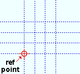
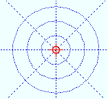
2 .Locate- Pan -Return mouse bindings become active along with various Locate options. Locate a reference point based on the type of construction grid that you are adding. The symbol in the examples below is centered on the location of the reference point.
Alternative 1 : Select the Locate icon that you want (if it's not pressed already). Place the mouse pointer ( ) so the point location target ( ) snaps to where you want the corner of a rectangular grid (or the center of the radial grid ), then left-click ( Locate ).
Alternative 2 : Right-click ( Return ) if you are done adding rectangular or radial construction grids. Do not continue.
3 . The Add Construction Grid window opens.
3a : If you want to end this operation at this point, simply press " Cancel ." To add a construction grid, first select the type of grid (' Rectangular grid ' or ' Radial grid '), then set the number and spacing of the construction lines and/or construction circles. Press " OK " to go to step 4 .
4 . After you press " OK " in the step 3, the construction grid is generated on your computer screen. Locate - Repeat - Returnmouse bindings become active. Do one (1) of the following:
Alternative 1 : Middle-click ( Repeat ) to cause an exact duplicate of the grid to be drawn over wherever the point location target ( ) is at.
Alternative 2 : Right-click ( Return ) to get out of the tool and bring back whatever mouse bindings were active before you invoked Add Construction Grid
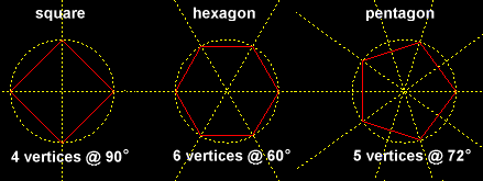
" Circle radius spacing or radii " and " Radial lines or starting " allow comma-separated entries, thus enabling you to apply variable construction circle radii or variable construction line rotations to a radial grid.
If you accidentally do a left-click ( Locate ) when you actually want to end this operation, you can press " Cancel " on the Add Construction Grid window to end the operation.
In multi-user environments, any construction lines/circles that you add will be seen by you only. They will be retained -- also for you only -- across Modeling sessions.
 Construction Line Add Grid Command
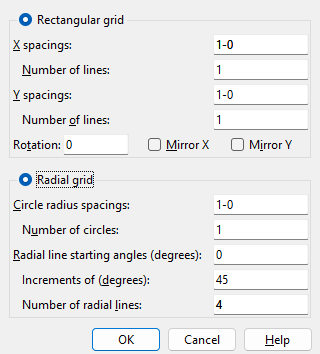
or
. If this box is checked (
Learn more about alternative methods for launching commands.
) so the point location target (
) snaps to where you want the corner of a rectangular grid (or the center of the radial grid ), then left-click ( Locate ).